 Аудио-википедия
База знаний по hi-fi и high-end технике и комплектующим, отзывы и впечатления
Инструменты пользователя
Боковая панель
4amps:6pit:lc-фильтр
LC-фильтр
Схема:
С дополнительным подавлением RC цепочкой:

Программа для расчета БП
Материалы по теме
Преимущества использования
https://www.audioasylum.com/messages/tubediy/165030/choke-input-power-supplies-part-1
Читать дальше
Choke-input power supplies, Part 1
Posted by Henry Pasternack on April 20, 2009 at 10:56:11
Introduction
I said earlier I would write about choke-input power supply design. This is a subject I got very interested in about fifteen years ago. I read as many old books on the subject as I could find and tried to understand the important technical factors. Given the atmosphere around here I feel as though I ought to make a disclaimer. I know from personal experience it's possible to build amplifiers with «conventional» choke-input supplies that sound very, very good. I can't say in any given application that some other configuration might not work better. There are too many interdependencies and personal subjective preferences to make hard and fast rules. When I start a project, whether it's an audio project or not, it's because I have an idea and I want to see how it works in practice. Usually I spend a lot of time on research and thinking through what I plan to do until I'm comfortable that I understand the project at a thorough nuts-and-bolts level. Then I build it, and often there are surprises and things that need to be rethought. But finally I'm done and I have some results. It's usually pretty good and usable, and I'm satisfied and have no urge to tear the thing apart and tweak it. That's just me, and others may seek different rewards.
My goal here is to give useful information about how power supplies work, perhaps to help people build and evaluate their own designs. I make no claims as to one thing sounding better than another. I know there are many, many different ways to build good-sounding amplifiers.
OverviewPosted by Henry Pasternack on April 20, 2009 at 10:56:11
Introduction
I said earlier I would write about choke-input power supply design. This is a subject I got very interested in about fifteen years ago. I read as many old books on the subject as I could find and tried to understand the important technical factors. Given the atmosphere around here I feel as though I ought to make a disclaimer. I know from personal experience it's possible to build amplifiers with «conventional» choke-input supplies that sound very, very good. I can't say in any given application that some other configuration might not work better. There are too many interdependencies and personal subjective preferences to make hard and fast rules. When I start a project, whether it's an audio project or not, it's because I have an idea and I want to see how it works in practice. Usually I spend a lot of time on research and thinking through what I plan to do until I'm comfortable that I understand the project at a thorough nuts-and-bolts level. Then I build it, and often there are surprises and things that need to be rethought. But finally I'm done and I have some results. It's usually pretty good and usable, and I'm satisfied and have no urge to tear the thing apart and tweak it. That's just me, and others may seek different rewards.
My goal here is to give useful information about how power supplies work, perhaps to help people build and evaluate their own designs. I make no claims as to one thing sounding better than another. I know there are many, many different ways to build good-sounding amplifiers.
What makes a power supply a choke-input supply, evidently, is the filter. The filter is a block of components that sits between the power transformer/rectifier and the amplifier circuit. This is true in general for all power supply filters, regardless of their type. The filter has four main functions, different but related. They are:
1) Provide a load on the rectifier such that it switches on and current flows, in one direction, out of the transformer and into the filter.
2) Store up the charge that comes out of the transformer and deliver it to the load even if the rectifier is not conducting.
3) Provide a low source impedance to the active circuitry at all frequencies from DC to the ultrasonic.
4) Reject hum and noise and keep it from getting through to the power supply output.
Читать дальше
So, you could say that a power supply is «good» if it does all of these things well. But everything is a compromise and we may not know for sure which of these factors is most important in a given application. That is where the designer's judgment comes in. I believe the better you understand the problem in theory, the better you are prepared as a designer to make design choices and to evaluate subjective performance results.
What you have here is basically a brain dump of everything I can think of to say about this subject. Because of the amount of material, I will have to do this in parts. It's a snapshot of how I think about the problem, not necessarily a recipe for design. I hope someone finds it interesting or useful.
Rectifier Load
The rectifier is a switch, which is a non-linear component. The rectifier only conducts when there is a positive voltage difference between the transformer secondary and the filter input. It is physically impossible for a single rectifier diode to conduct throughout the entire secondary sinewave cycle. It is also impossible for current to flow backwards out of the filter into the transformer. The diode will always turn off at some point. The current drawn from the rectifier, and the voltage waveform that appears on the filter input terminal, depend strongly on the electrical characteristics seen by the rectifier looking into the filter and on the DC load current drawn from the supply. The DC voltage at the output of the filter, in turn, depends on the shape and the amplitude (that is to say, the average value) of the filter input voltage waveform. If the average DC input voltage changes substantially with load current, the supply will have poor regulation.
In this sense, the transformer, rectifier, and first filter input component are like a kind of complex, ratcheting electrical machine which functions to turn the AC voltage coming out of the transformer into a raw form of DC that can be purified. The complexity of the interaction between these three components is what makes the filter topology and especially the value of the first filter component so important to the performance of the supply.
The main distinction between a choke-input filter and a cap-input filter is that the choke-input filter loads the rectifier so that current flows into the filter almost continuously. If the choke were infinitely large, the current would be constant DC. With a practical choke, the current into the filter consists of a DC component equal to the DC load current with a superimposed AC current approximately equal to the ripple voltage divided by the choke impedance, summed across all the harmonics of the AC supply frequency.
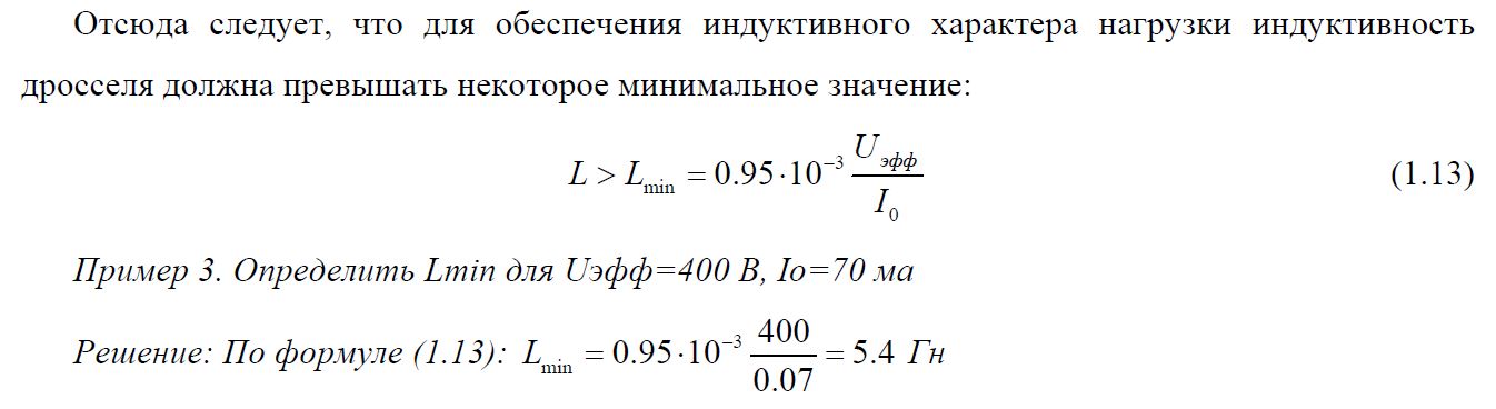
This helps explain the definition of «critical inductance». Ignore the higher order harmonics and only consider the dominant 120Hz (or 100Hz) component of ripple voltage. The first capacitor following the choke, if it is large enough, looks pretty much like a short at this frequency. So the entire ripple voltage appears across the choke and the resulting current is proportional to the ripple voltage and inversely proportional to the choke inductance at the ripple frequency. The higher the voltage or the smaller the choke, the greater the ripple current. To keep the choke conducting, the DC current bias has to be large enough that the negative peaks of the ripple current never reach zero. It is possible to derive a simple, approximate formula for the the minimum inductance to give continuous rectifier conduction as a function of DC load current. The familiar formula is:
Lcrit = Vdc / Ima
where Lcrit is the minimum (critical) choke inductance, Vdc is the supply DC output voltage, and Ima is the load current in milliamperes.
There are three main reasons continuous current conduction is important. The first is that a continuous current with a lower peak value makes more efficient use of the power transformer. This is because power lost to heat is a function of the square of the instantaneous current. You generate less heat conducting a lower current for a longer time than a higher current for a proportionally shorter time.
The second reason is that the smooth, relatively low peak supply current creates less switching noise and electromagnetic interference to pollute the signal circuitry.
The third reason is that continuous current conduction gives much better DC voltage regulation. This is because the duty cycle of the filter charging current doesn't vary as long as the load current exceeds the minimum threshold as calculated by the critical inductance formula. And therefore, the filter input voltage waveform is constant, and the average DC input voltage is constant, too. Contrast this with a cap-input filter where the charging duty cycle is a function of load current. This is a bit of a subtle point and may deserve some follow-up discussion. In the old days, when large filter capacitors were not available, improved regulation was a major advantage of the choke-input filter. This distinction is less important nowadays.
In practice, the diode conduction current is not continuous. This is because diodes do not conduct until their minimum forward voltage drop is exceeded. So even with a critical choke-input filter there is a dead zone in the conduction waveform and the potential for generating switching noise. Solid-state diodes can also conduct backwards momentarily as minority carriers get swept away, creating another source of switching noise. But the noise in general is less than that produced by a cap-input filter, and there are techniques for «snubbing» the noise (e.g., as documented by Jones in «Valve Amplifiers»).
To summarize, we can say overall, from the point of view of efficiency, noise generation, and regulation, the choke-input filter provides a superior interface to the rectifiers, and this may be a factor in the subjective perception that choke-input filters give better sonic performance.
Выбор дросселя
https://www.aikenamps.com/index.php/chokes-explained
How to select a choke:
Chokes are typically rated in terms of max DC current, DC resistance, inductance, and a voltage rating, which is the max safe voltage that can be applied between the coil and the frame (which is usually grounded).
<hidetext Читать дальше>
DC current
If you are using a choke-input filter (not likely, unless you are trying to convert a class AB amp to true class A and need the lower voltage, or if you are designing an amp from scratch and want better supply regulation), the choke must be capable of handling the entire current of the output tubes as well as the preamp section. Note that this doesn't mean just the bias current of the output tubes, but the peak current at full output. This usually requires a choke about the size of a standard 30W-50W output transformer, since the choke must have an air gap (just like a single-ended OT) to avoid core saturation due to the offset DC current flowing through it, and the choke also must have a low DC resistance, to avoid dropping too much voltage across it, which will lower the output voltage and worsen the load regulation. This combination of low DCR, air gap, and high inductance (more on that later…) usually results in a substantial sized choke. To calculate the required current rating, add up the full power output tube plate currents, screen currents, and the preamp supply currents, and add in a factor for margin. For a 50W amp, this may be 250mA or so.
If, on the other hand, you are selecting a choke for a capacitor input supply (such as the typical Marshall or Fender design), then the requirements are relaxed quite a bit. The purpose of the choke in these type supplies is not for filtering and voltage regulation, but just for filtering the DC supply to the screen grids of the output tubes and the preamp section. The screens typically take around 5-10mA each, and the preamp tubes draw about 1-2mA or so (for the typical 12AX7; 12AT7's are usually biased for around ten times that). This means that you can get by with a much smaller choke, and, in addition, the preamp supply current doesn't vary that much, so you can get by with a higher DC resistance, which means smaller wire can be used to wind the choke, which means higher inductance for a given size core. Just add up the current requirements of the screens and preamp tubes, and add a bit more for margin. For a 50W amp, a typical value might be 50-60mA.
DC resistance
For a typical choke input supply, you need a choke with no more than 100-200 ohms or so DCR. A capacitor input supply typically might use a choke with a 250 ohm - 1K DCR. The higher the resistance, the more voltage drop and the poorer the regulation, but the cost will be lower.
Inductance
As for the inductance value, this depends on how much filtering you want. The inductance, in conjunction with the filter capacitance, forms a lowpass filter. The larger the inductor, the lower the cutoff frequency of the filter, and the better the rejection of the 120Hz (if full wave rectified) or 60Hz (if half wave rectified) AC component of the rectified DC. In general, the larger the better, within reason (larger inductances at low DC resistances mean larger chokes, which cost more money). Typically, 5-20 Henries is a good choice with the standard 32-50uF electrolytic capacitors. The inductance and capacitance values also determine the transient response of the supply, which means the tendency for the supply to overshoot or «ring» with damped oscillations whenever a current transient is applied (such as at startup or on a heavy current surge, such as a hard «E» chord at full power!).
Voltage rating
The voltage rating must be higher than the supply voltage, or the insulation on the wire may break down, shorting the supply to the frame.
I highly suggest going to Duncan Munro's website (http://www.duncanamps.com/ ) to download his power supply calculator program. It will allow you to experiment with different inductance and capacitance values and see the resulting residual AC ripple and transient response of the supply filter. Both capacitor input and inductor input filters can be simulated. It is a great educational tool.
http://education.lenardaudio.com/en/14_valve_amps_6.html Choke input filter
The primary limitations of early valve rectifier power supplies was the high forward resistance in the rectifier valves and the small storage capacity of the Electro's (approx 20uF). 470uF Electro's are often used in high quality valve amps today.
Most valve amps above 40 Watt are configured in Class AB (Negative bias). The quiescent current through each output valve is approx 50mA. When the amp is driven to full power the current can increase to approx 150mA. The B+ Voltage from a traditional Capacitor input supply will readily drop to a lower level. The B+ Voltage will be modulated by the varying current through the output valves. As the B+ Voltage reduces, so does the gain of the output valves. A modulating B+ Voltage causes massive inter-modulation distortion.
Choke input filter power supplies, also referred to as Swinging choke power supplies, are often seen in industrial electronics where a large amount of DC current is required with high regulation. Choke input filter supplies were often used in early valve rectifier power supplies for 100+ Watt valve amps. The Swinging choke is nearly as large as the power tranny. Two extra large valve rectifiers were often used. Each valve rectifier has the Anodes in parallel to reduce its internal resistance, enabling greater current.
Swinging choke power suppy
The pulsating DC from the rectifier valve goes through a large Choke (non saturable Inductor). The Swinging choke converts the pulsating DC to its RMS value without loosing energy. The internal losses in the 2 valve rectifiers is minimal. AC to DC conversion is close to the academic formula.
AC Volts x 0.9 = DC Volts
640V AC x 0.9 = 576V DC
Читать дальше
A Choke input power supply is approx 90% efficient, therefore the B+ will remain relatively stable when a Class AB amp is driven at high power. In the above circuit, 16V loss is caused by the forward resistance of the 2 large valve rectifiers. 16V valve rectifier loss is small compared to B+ 560V.
The advantage of Choke input supply is its excellent regulation and minimal pulsating DC ripple on the B+ Voltage. In the earlier times when only small Electro's were available (20uF) increasing the Inductance of the choke could directly compensate for the small value Electro's. A Choke input filter using modern lager 470uF Electro's can achieve a close to perfect ripple free B+ supply.
CIP disadvantage. Choke input filter supply must have a load on it at all times for it to stabilise. Without a load, a Choke input filter supply will behave as a capacitor input supply and the B+ Voltage will raise to the peak of the pulsating DC Voltage. In the example power supply, 640V AC x 1.414 = 904V DC. It is essential to have an external resistive load on the B+ output, at all times, or have a circuit that switches a resistive load onto the B+ if the amp is turned on without the output valves.
Swinging choke The term «Swinging choke» was often used to represent Choke input filter supplies in valve amps. In industrial electronics the term Swinging choke is used to represent the smallest physical size a choke can be to stabilise the DC current (requires further explanation). A large linear choke is normally used for valve amp power supplies, not a small swinging choke.
https://el34world.com/Forum/index.php?PHPSESSID=7itm19jj08hjksv28ebkb1ujs7&topic=622.msg1936#msg1936
I went to a reliable source (Morgan Jone's book Valve Amplifiers) and looked up some choke-input supply info. He notes that in the «old days» the solution was to use a swinging choke. You have a very tough time finding those these days, so that's probably out of the question.
He gives a detailed formula for the minimum current draw needed, but then goes on to note an approximation for 50/60Hz power supplies. It's Current min. (in milliamps) = VIn (RMS) / L (in henries). So for your 500vac transformer (which is RMS volts), you'd divide that 500v by the inductane rating of the choke you intend to use to see what the minimum current draw must be. As an example, for a 20H choke, 500v/20H = 25 milliamps of minimum current draw. The implication is you want a very high inductance rating for your choke.
He also notes that it would seem the choke only needs to be rated for the maximum d.c. load current, but that the choke really needs to be rated in excess of this. Why? The choke generates a magnetic flux in the core proportionate to the size of the current passing through it, and if that flux is too great, it saturates the core and the inductance of the choke falls to zero. Bam! You're back at 700v.
The current that the choke will support is the max d.c. load current and the instantaneous a.c. charging current (meaning the current used to charge the filter caps). So that's
IDC + IAC = Itotal peak current.
He derives a formula for the a.c. peak current. For a 60Hz wall outlet, it's
IAC (positive peak) = VIn (RMS) / [1386 * L)
Vin is the RMS transformer voltage again, and L is choke inductance in Henries.
Читать дальше
Here's an example he gave in the book, but with a slightly different formula for 50Hz operation:
«A Class A power amplifier using a pair of push-pull 845 valves requires a raw HT of 1100v at 218mA, and a 10H 350mA choke is available, but is this adequate? The transformer supplying the choke has an output voltage of 1224VRMS, and using the equation for a 50Hz mains:
IAC = VIn / 1155 * L = 1224 / (1155 * 10) = 106mA
Itotal peak current = IDC + IAC = 218mA + 106mA = 324mA
The total peak current is 324mA, so the 350mA is just barely sufficient … «
That shows that the choke needs to be rated in excess of the peak d.c. load current, which is the current the amp draws from the power supply at max power, not at idle. Once again, a choke with more inductance tends to ease your required ratings. But in all, you need to flesh out the design a bit more to properly rate the choke. Looking at this info, it's a very bad idea to just «slap something in» when you're thinking about a choke-input power supply. Jones also notes that regarding the power transformer, it simply needs to be rated for the d.c. load current. He gives an explanation for why, but it's enough to know that's the case. He does also note that the input choke creates voltage spikes seen by the power transformer. The solution is to have a snubber network, and he notes that the apparently best way of going about this is to fit 2 caps across the choke, with their «center-tap» connected to 0v. What this means is to use two 0.22uF 1kV caps connected in series, then take the outer leads and connect those to the choke to put this pair of caps in parallel to the choke, then connect the junction of the 2 caps to ground.
С сайта Вестерн Электрик
https://www.westernelectric.com/products-274b.html
It is evident from the regulation characteristics of Figures 4 and 5 that for a given output current and voltage, the choke-input filter requires a somewhat higher alternating voltage applied to the plates of the tube than the capacitor-input filter. With the capacitor input filter, however, the normal charging and discharging of the capacitor each half cycle requires the tube to supply relatively large peaks of current during each charging period. The peak current increases in value as the capacitance of the capacitor is increased and may be much larger than the average rectified output current, though its duration in such cases is only a short fraction of a cycle. Since for good tube performance, the anode current must be considerably less at every part of the cycle than the total emission current from the filament, the maximum permissible output current must be limited to such a value that this condition is satisfied. The permissible output current may be larger, therefore, for a choke-input filter, in which the peak anode current is only slightly larger than the output current. The choke-input filter also gives much better regulation than the capacitor-input circuit. The choke-input filter, therefore, should always be selected in preference to the capacitor-input filter wherever possible. With a capacitor-input filter, the capacitance of the input capacitor should preferably not exceed 4 microfarads.
BOFH
Опубликовано: 4 мая 2008
Ден 123 писал:
Привет.
У меня SE 6С4С. 4 отдельных
выпрямителя, 2 обмотки на каждый
канал своя. Ставил Г фильтры на
драйверы особой разницы не заметил.
С Г фильтром на выходных лампах
драйва добавилось, усилитель стал
более "ритмичным", детальность
возросла, но в целом ощущение, что
картинка "развалилась".
Вернул СЛС обратно. Причем с
расстройства воткнул Мбгч 20 мкф
вместо электролитов. Стало заметно
"свежее", немного посравнивал с
электролитами 100х450. Оставил МБГЧ.
Отсюда у меня вопрос не в тему ветки
ко всем: может быстрые конденсаторы
надо ставить сразу за выпрямителем,
а не только шунтировать ими выходные
кондесаторы фильтра?
Доброго времни суток, Уважаемые)
В моём случае с Г-фильтром в преде стало ЗНАЧИТЕЛЬНО лучше, при том же др. и тех же фильтрующих емкостях.
«Быстрые конденсаторы» НАДО ставить сразу за выпрямителем (0.1-0.8uF), можно и без них, но оч точно придётся подгонять L, у Сергея Рубцова это наглядно описано.
Сам за несколько ночей перепробовал кучку разных типов и номиналов. Тут безусловно всё индивидуально, но на звук оказывают влияние весьма и весьма существенное, полностью с Сергеем согласен.
Александр, к Вам вопрос как к автору генеального нововведения в аудио БП ака «синхронный выпрямитель» отчего же ему Г-фильтр контрадишн? Мои скромные эксперименты показывают что скорей Г-фильтр есть отличное дополнение и как раз 3его зайца-то и убиваем.
Сейчас так и слушаю в преде, звучит просто потрясающе)) В каждом канале ДППВ на ульрафастах + синхронник на двух 19ах, накопительные по 8uF полипропилен в масле + 0.1uF ССГ-2 дальше ФТ-3 0.47uF + 0.1uF ССГ-2 - 7.5Hn - 6600uF Rifa + шунты-шмунты.
И это притом что дроссели мягко говоря не то - 150 Ohm ! Буду менять на 30-40 Ohm. И ещё не пробовал ставить/подбирать R-слива.
4amps/6pit/lc-фильтр.txt · Последнее изменение: 2020/05/20 23:58 — staudio
Инструменты страницы
Если не указано иное, содержимое этой вики предоставляется на условиях следующей лицензии: CC Attribution-Share Alike 4.0 International

Обсуждение
BRIDGE LC Vac = Vdc x 1.11 Iac = Idc x 1.06 Pac = Pdc x 1.18
FULL WAVE LC Vac = Vdc x 2.22 Iac = Idc x 0.65 Pac = Pdc x 1.44
BRIDGE CLC Vac = Vdc x 0.71 Iac = Idc x 1.61 Pac = Pdc x 1.14
FULL WAVE CLC Vac = Vdc x 1.41 Iac = Idc Pac = Pdc x 1.41
https://www.sowter.co.uk/rectifier-transformer-calculation.php