 Аудио-википедия
База знаний по hi-fi и high-end технике и комплектующим, отзывы и впечатления
Инструменты пользователя
Боковая панель
4amps:6pit:lc-фильтр
Это старая версия документа!
LC-фильтр
Схема:
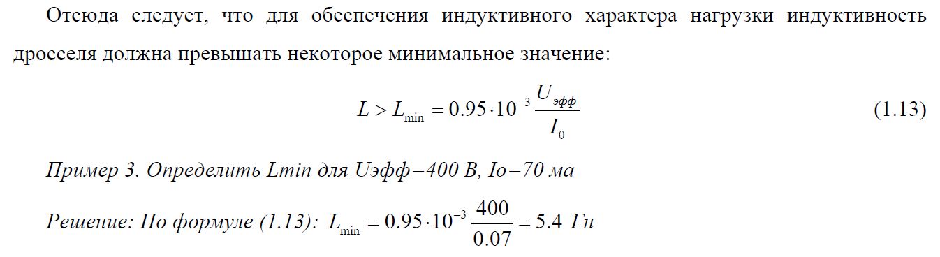
Формула рассчета:
 Программа для расчета БП:
http://www.duncanamps.com/psud2/
Choke input filter
The primary limitations of early valve rectifier power supplies was the high forward resistance in the rectifier valves and the small storage capacity of the Electro's (approx 20uF). 470uF Electro's are often used in high quality valve amps today.
Most valve amps above 40 Watt are configured in Class AB (Negative bias). The quiescent current through each output valve is approx 50mA. When the amp is driven to full power the current can increase to approx 150mA. The B+ Voltage from a traditional Capacitor input supply will readily drop to a lower level. The B+ Voltage will be modulated by the varying current through the output valves. As the B+ Voltage reduces, so does the gain of the output valves. A modulating B+ Voltage causes massive inter-modulation distortion.
Choke input filter power supplies, also referred to as Swinging choke power supplies, are often seen in industrial electronics where a large amount of DC current is required with high regulation. Choke input filter supplies were often used in early valve rectifier power supplies for 100+ Watt valve amps. The Swinging choke is nearly as large as the power tranny. Two extra large valve rectifiers were often used. Each valve rectifier has the Anodes in parallel to reduce its internal resistance, enabling greater current.
Swinging choke power suppy The pulsating DC from the rectifier valve goes through a large Choke (non saturable Inductor). The Swinging choke converts the pulsating DC to its RMS value without loosing energy. The internal losses in the 2 valve rectifiers is minimal. AC to DC conversion is close to the academic formula.
AC Volts x 0.9 = DC Volts 640V AC x 0.9 = 576V DC
A Choke input power supply is approx 90% efficient, therefore the B+ will remain relatively stable when a Class AB amp is driven at high power. In the above circuit, 16V loss is caused by the forward resistance of the 2 large valve rectifiers. 16V valve rectifier loss is small compared to B+ 560V.
The advantage of Choke input supply is its excellent regulation and minimal pulsating DC ripple on the B+ Voltage. In the earlier times when only small Electro's were available (20uF) increasing the Inductance of the choke could directly compensate for the small value Electro's. A Choke input filter using modern lager 470uF Electro's can achieve a close to perfect ripple free B+ supply.
CIP disadvantage. Choke input filter supply must have a load on it at all times for it to stabilise. Without a load, a Choke input filter supply will behave as a capacitor input supply and the B+ Voltage will raise to the peak of the pulsating DC Voltage. In the example power supply, 640V AC x 1.414 = 904V DC. It is essential to have an external resistive load on the B+ output, at all times, or have a circuit that switches a resistive load onto the B+ if the amp is turned on without the output valves.
Swinging choke The term «Swinging choke» was often used to represent Choke input filter supplies in valve amps. In industrial electronics the term Swinging choke is used to represent the smallest physical size a choke can be to stabilise the DC current (requires further explanation). A large linear choke is normally used for valve amp power supplies, not a small swinging choke.
4amps/6pit/lc-фильтр.1582628946.txt.gz · Последнее изменение: 2020/02/25 14:09 — staudio
Инструменты страницы
Если не указано иное, содержимое этой вики предоставляется на условиях следующей лицензии: CC Attribution-Share Alike 4.0 International

Обсуждение
BRIDGE LC Vac = Vdc x 1.11 Iac = Idc x 1.06 Pac = Pdc x 1.18
FULL WAVE LC Vac = Vdc x 2.22 Iac = Idc x 0.65 Pac = Pdc x 1.44
BRIDGE CLC Vac = Vdc x 0.71 Iac = Idc x 1.61 Pac = Pdc x 1.14
FULL WAVE CLC Vac = Vdc x 1.41 Iac = Idc Pac = Pdc x 1.41
https://www.sowter.co.uk/rectifier-transformer-calculation.php